Fabrication as a service is only as good as the drawings that fabrication is based on. A simple fabrication drawing must be precise in order to be easily understood and ultimately effective when viewed and followed by the shop. There are various levels of detail and quality involved, especially as you debate fabrication drawing versus shop drawing, but the following information should help you create single part drawings, mechanical part drawings and technical drawings that yield the results that you want.
Managing Different Views
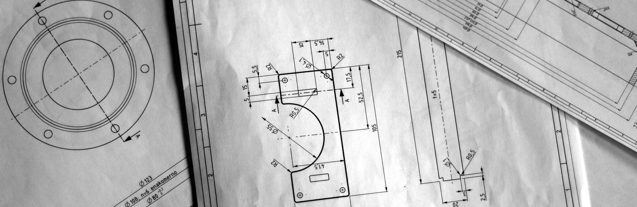
A simple fabrication drawing includes various views from different perspectives. By sharing multiple views, the shop doing the fabrication can see the part or component from different angles and gain as much information as needed in order to match the designs. The different views included in technical drawings are:
- Axonometric: Axonometric views are three-dimensional in nature, and they provide a simple, comprehensive perspective. It’s best to include at least one axonometric view per drawing. This view shows as many parts of the component at one time as possible, giving the shop doing the fabrication a comprehensive view of the component to be created. Do not add dimensions to axonometric drawings, as they can make this view overly complicated and ultimately misleading.
- Orthographic: Orthographic views illustrate components with various pieces that are rotated 90 degrees from one another. Start by choosing a “front” side of the component to illustrate first and to make most prominent. Then add the side, rear, top and bottom views of the component to be fabricated as needed.
- Sectional: Sectional views show through the component from the most prominent side. For maximum impact, consider setting sectional view illustrations next to their corresponding orthographic view illustrations.
- Assembly: Assembly view illustrations are important when fabrication includes putting together different parts of a system. By showing the shop the assembly process at the start of a project, they will be able to identify the most efficient process for creating the various parts.
The views listed above are commonplace, though the specific views you’ll need to use will depend on the nature of your project. For example, single part drawings may require different views and information than mechanical part drawings.
The Importance of Dimensions
With any simple fabrication drawing, it’s important to convey as much information as possible in a clear fashion. Dimensions, of course, are among the most important pieces of information to be conveyed to the shop doing the fabrication, so make sure you are marking dimensions clearly.
All distances should be listed with arrows headed at both ends along the length of the component. Only indicate distances one time — listing them multiple times can be confusing and lead the fabricator to assume there’s a difference where there isn’t one. Keep your technical drawings as simple as possible by listing all dimensions from a single view. And ensure that your dimension lines never cross one another, as this can make it harder to understand them.
To separate hole dimensions from distance dimensions, mark them with a single-headed arrow only. Make sure that you always describe the four important pieces of information related to any hold: diameter, depth, shape of bottom and type of thread, if applicable.
Indicating Tolerances
Even the best, most precise fabrication process will result in a final component that doesn’t exactly match the plans. That’s where tolerances come into play. How much tolerance can be included so that the component still functions as desired?
Think of tolerances as a range of values within which the final specifications need to fall. Most tolerances are expressed as plus-minus. For example, +/-0.1” means the tolerance is one-tenth of an inch above or below the distance stated in the simple fabrication drawing. How you indicate tolerances in the actual drawings is up to you, as long as they are marked clearly and as long as they do not make other information in the drawings more difficult to understand.
The more professional the fabricator, the less tolerance is needed for successful completion of a project. While an amateur fabricator may work with +/-.05” or +/-.01” tolerances, professionals using advanced tools and machines can often reduce tolerance to +/-.001” or +/-.0005”. When tolerance is limited to this degree, fabricated components meet higher quality standards and work better within larger plans.
APX York Sheet Metal — Your Fabrication Experts
Are you looking for a fabrication partner that can follow simple fabrication drawings and deliver the results you need? At APX York Sheet Metal, we can be that fabrication partner. We’re a trusted service provider that gets the job done.
Our specialties include material handling equipment components, construction equipment, custom metal fabrication, electrical boxes and panels, OEM manufacturing parts, industrial cabinets and enclosures, battery cabinets, conveyor belt systems and more. To ensure adherence to specifications, we use laser cutting, bending, welding, grinding and powder coating as key steps in the fabrication process. We take your plans and do what it takes to make them a reality.
Family-owned and operated, APX York Sheet Metal brings more than 71 years of industry experience to each job. When you want quality components and reliable service, choose APX York Sheet Metal as your fabrication partner. Reach out to us online to learn more about how we can help bring your drawings to life.
